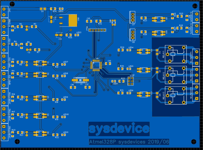
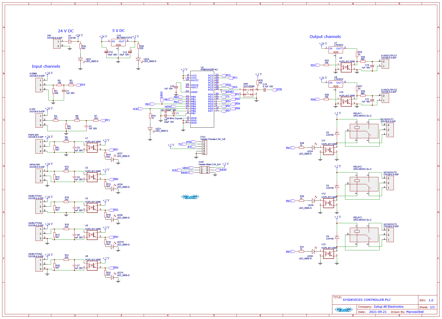
This is an inexpensive programmable logic controller project that performs control and monitoring functions for industrial processes of various types and levels of complexity, through specific programs developed by the user


Technologies | How To Use | Do It Yourself | License
This project is still in the development stage and using the following technologies
During its operation, the PLC carries out a sequence of operations called a scan cycle. The time the PLC takes to complete a cycle is called the Scan Time or Scan Time, providing a scan time of approximately 1024 (1K) Boolean logic instructions[1]. All tasks performed by the processor are performed sequentially and cyclically while being powered.
When it is turned on, the PLC performs a series of pre-programmed operations: it checks the electronic functioning of the CPU, memories and auxiliary circuits; Check the status of the main input and output switches and check the existence of a pre-programmed user program in the ATMEGA328P microcontroller
The PLC reads the states of each one of the inputs, checks their respective triggers and updates their states in the outputs if the stored user program was created with deterministic conditions
The PLC stores the results obtained during processing and compares them with the instructions defined in the user program. The PLC writes the value contained in memory to the outputs, updating the interfaces or output modules, that is, it turns the outputs on or off according to its program. Then a new sweep cycle starts. Analog signals are level variations from a minimum value to a maximum value.
Example:
0 to 10V (Volts)

-10 to +10V
In registers we can store values of up to 16 bits of resolution, thus occupying the 4 digits. If the resolution is 1bit – It means that we can split the analog signal into two (2) states “0” and “1”.
Example:
0V = 0 10V = 1 (but in this case the signal is still considered digital).If 2bit resolution – Means that we can divide the analog signal into four (4) states
“00”, “01”, “10” and “11”.Example:
0V = 00; 3.3V = 01; 6.6V = 10; 10V = 11.So the more bits of resolution, the more parts we can divide the analog range. For each PLC there are registers associated with the analog inputs and outputs and the contents of these registers change instantly as the analog signal changes. Analog values are read from the PLC as 'word' format information. Access to these words is carried out, for example, with the operands:
%IW 64 = Analog Input Word 64%QW 80 = Analog output word 80Each analog value ("channel") occupies an input or output word. The format is 'Int' an integral integer. The addressing of the input or output words is oriented according to the addressing in the device view. When an analog input value is available with the digitized value, it usually still needs to be normalized so that the numerical values match the physical variables of the process. Likewise, the analog output takes place in the peripheral output word only after normalization of the output value. This project directory contains a folder with its respective version (in a subfolder), the electronic schematic and the layout of the printed circuit board (PCB) and compiled code, which is specific to each function of the 8bit computer.
Always check and/or use the highest numbered version or most recent modification described in the commit for example:
To clone and download all project directories you can use Git, or any other specific program. To clone the current directory use the command:
# Clone this repository
$ git clone https://github.com/aragonxpd154/sysdevice-plcYou can use the Arduino Uno bootloader, if you need to work in an internal Arduino compatibility environment for those who do not have a mastery of microcontroller programming
To burn the bootloader, you will need to buy an AVR-ISP (system programmer), USBtinyISP or build a ParallelProgrammer. The programmer must be connected to the ICSP pins (the 2 by 3 pin connector) - make sure you connect it correctly. The board must be powered by an external power supply or USB port.
Make sure you have the correct item selected in Tools | Board menu. Then just launch the appropriate command from the Tools > Burn Bootloader menu from the Arduino environment. Burning the bootloader can take 15 seconds or more, so be patient.
You can find the respective bootloaders at https://github.com/arduino/ArduinoCore-avr/tree/master/bootloaders
This project is under the MIT license. See the LICENSE for more information.
Made with ♥ by Marcos (Obel) 👋 Get in touch!