This repository contains functions and examples designed for Arduino enthusiasts (especially ESP8266 users) to read, write, and format NTAG213 tags using a PN532 based reader.
The PN532 is a well supported chip that was made into various modules by creators such as Seed Studio, Adafruit, and Elechouse. The hardware modules are very nicely designed by these companies. However, the approach to making a working implementation using a PN532 reader with an ESP8266 microcontroller is not so direct. It is even more rare to find examples on how to read, write, and erase the memory on an NTAG213 tag (NFC forum type 2) using this implementation. These are all very common items and can be purchased on Amazon or eBay.
There are many ways to interface with the PN532 such as HSU (UART), SPI, and I2C. The aim of this repository is not to "fork" or recreate any existing work. It is not to create a bias toward any type of RF tag whatsoever. It is rather to share my reliably implemented functions and examples of storing various pieces of text on an NFC tag and reading them quickly.
Having read forums and stories of people with trouble getting reliable NFC readings, I took the challenge of creating my own examples and tutorial for getting this to work. Although NFC is still not supported in some phones, it is widely supported by name brands. By making hardware that uses NFC to connect, we can easily share information between keychains, cups, and other NFC-enabled objects.
The goal is to aim for a simple setup. If possible, my preference was to aim for I2C communications on the PN532. However, it seems that the I2C implementations on these libraries do not play well with the ESP8266 because apparently the PN532 uses clock stretching and the microcontroller does not have hardware capabilities. Although we could use a library for I2C clock stretching (such as https://github.com/pasko-zh/brzo_i2c), I decided to go with an easier approach which is HSU (UART).
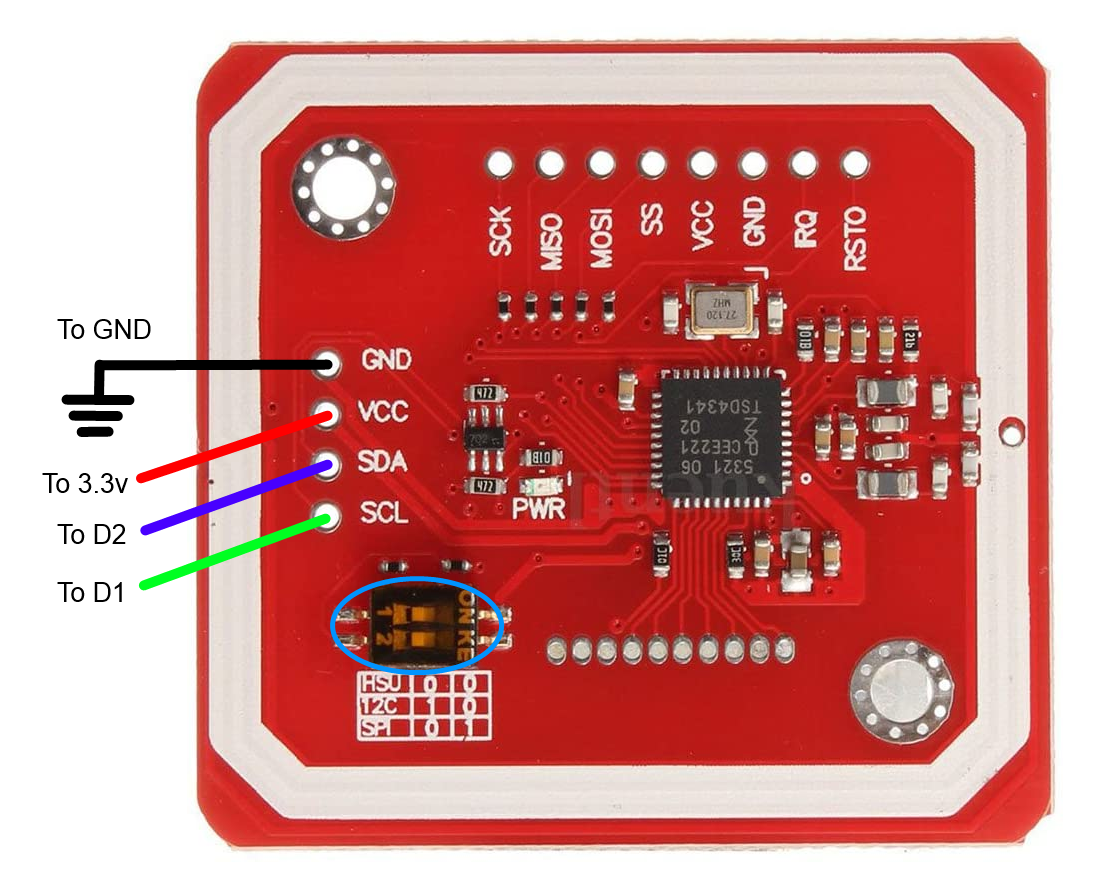
The PN532 module has a mode called HSU which is high speed UART. To use HSU mode, flip both dip switches to OFF. So now we can now interact via UART.
Connect the PN532 module using pins such as D2 for RX and D1 for TX. In some cases, it would be helpful to solder 10k pullup resistors to these lines. In other words, a resistor from RX to 3.3V and another resistor from TX to 3.3V. This depends on the microcontroller you use.
Now connect 3.3V from ESP8266 to the VCC of PN532. Do not use 5V as this will take the logic levels to 5V which may fry the ESP8266. Connect the GND terminals. Refer to the wiring diaram for details.
Before we jump into the code examples, it is highly recommended to learn more about how to manipulate the data in an NFC tag such as NTAG213. This info is just enough to get you familiarized with some terminology and concepts to get an understanding of what the code does and how we will interact with it.
NFC tags start their formatting with something known as a Type Name Format Field (TNF Field). This is a 3-bit value that sets the type of data we will store in our tag. In all our examples, we will write using the Well-Known Record (0x01) identifier since we are just storing one or more lines of text.
In addition to providing a TNF field, we will also need to calculate the bytes of the total payload. The bytes of each string need to calculated too. If the calculation or formatting is wrong, then most NFC readers will fail to parse the data and throw an error or declare it as an empty tag. Normally, we will also need to assign an ID to every item we store. Finally, in your text payload, you must precede it with the bytes en before storing in the tag.
For example, if we wanted to send strings that contain "Text", we would have to send "enText". Header and footer bytes will be added to provide clarity. When writing more than one line of text, an a special byte such as (0x51) is used. However, for 3 or more items, the byte (0x11) is used to append text until the "next to last" item. The last append byte is always (0x51). You can read about these in the example codes.
Format Sequence:
[Header bytes first]
1 line: enText + FE
2 lines: enText + 51 + enText + FE
3 lines: enText + 11 + enText + 51 + enText + FE
4 lines: enText + 11 + enText + 11 + enText + 51 + text + FE
Additional lines of text will follow this convention. On an NTAG213, there are typically 36 user pages you can write to. A page is known as 4 bytes. A byte can be an ASCII character, hex, or an integer (from 0-255).
Persistent data gets stored in the first 4 pages (16 bytes) of the tag. This is why we only start accessing and writing data at the page index 4. We have around 32 pages (128 bytes) that can be written to, excluding the headers which usually take up a couple pages. This gives us plenty of space to store a few names, shortened URLs, and ID numbers.
Storage Format
One line: (length = 13)
 01 03 A0 0C    ....
 34 03 0D D1    4...
 01 09 54 02    ..T.
 65 6E 54 65    enTe
 78 74 20 31    xt 1
 FE 00 00 00    ....
Two lines: (length = 26)
 01 03 A0 0C    ....
 34 03 1A 91    4...
 01 09 54 02    ..T.
 65 6E 54 65    enTe
 78 74 20 31    xt 1
 51 01 09 54    Q..T
 02 65 6E 54    .enT
 65 78 74 20    ext
 32 FE 00 00    2...
Three lines: (length = 39)
 01 03 A0 0C    ....
 34 03 27 91    4.'.
 01 09 54 02    ..T.
 65 6E 54 65    enTe
 78 74 20 31    xt 1
 11 01 09 54    ...T
 02 65 6E 54    .enT
 65 78 74 20    ext
 32 51 01 09    2Q..
 54 02 65 6E    T.en
 54 65 78 74    Text
 20 33 FE 00     3..
Four lines: (length = 52)
 01 03 A0 0C    ....
 34 03 34 91    4.4.
 01 09 54 02    ..T.
 65 6E 54 65    enTe
 78 74 20 31    xt 1
 11 01 09 54    ...T
 02 65 6E 54    .enT
 65 78 74 20    ext
 32 11 01 09    2...
 54 02 65 6E    T.en
 54 65 78 74    Text
 20 33 51 01     3Q.
 09 54 02 65    .T.e
 6E 54 65 78    nTex
 74 20 34 FE    t 4.
The examples above show data ranging from payloads that contain 1 to 4 lines of text. The total payload bytes can be calculated by: total bytes - 8 because we exclude the first 8 bytes.
Now that we connected the PN532 module to the ESP8266, we will set up the Arduino IDE. If you have not done so already, download and install the PN532 library from Elechouse.
We won't use their examples but will need some code from their library. The main folders of their library we use will be PN532_SWHSU and PN532. You can exclude the other folders if you desire. The reason why we use PN532_SWHSU and not PN532_HSU is because we want to use custom pins for RX and TX using SoftwareSerial. You cannot upload to the ESP8266 when you block your main hardware serial pins.
The example NFC_getTagUID.ino reads an NFC tag to get its UID. This is an identifier that is unique, like a serial number. It is good for security and authentication purposes because it is difficult for UID to be forged.
The example NFC_readTag.ino reads the data of a tag and prints out the various text lines, which are stored in a string array.
The example NFC_writeTag.ino writes a string array to a tag and prints out the various lines written.
The example NFC_formatTag.ino will erase and format a tag (as long as it is not password protected).
The example NFC_functions.ino contains all the functions of the above examples. Using this as your next template, you can design new firmware for your project and be creative.
In this template, you have access to call these functions:
void readTag(bool verbose = true);
void writeTag(String textLines[10], int numLines);
void eraseTag(void);
void getTagUID(void);
However, prior to calling these functions, you must ensure a tag is near the reader. You can wait for a user to put a tag near the reader using this line:
    // wait until a tag is present
    while (!nfc.readPassiveTargetID(PN532_MIFARE_ISO14443A, uid, &uidLength)) {
      Serial.println("waiting for a tag");
      delay(1000);
    }
And you can wait until a tag is removed through this code:
    // wait until the tag is removed
    while (nfc.readPassiveTargetID(PN532_MIFARE_ISO14443A, uid, &uidLength)) {
      Serial.println("please remove tag");
      delay(1000);
    }
Don't remove the delay code or set it too low, as it can crash the ESP watchdog. A non-blocking solution will be coming soon.
Feel free to reach out to me if you have any questions or would like to request for a custom-solution.
If you are interested in buying a PN532 module from Elechouse: http://goo.gl/i0EQgd
Elechouse PN532 library: https://github.com/elechouse/PN532
Disclaimer: This project provides resources "AS-IS" and does not guarantee any compatibility with your project. No warranty is provided. The author is not affiliated with Elechouse or its associates. By building this project or using provided code, you acknowledge that you have basic knowledge of electronics and agree to take responsibility for any damages or injury at your own risk. You agree that the author will not be liable for any incompatibilities, damages, or injury as a result of this project.