This project is follow up for "ESP-RFID Board" but with few more options.
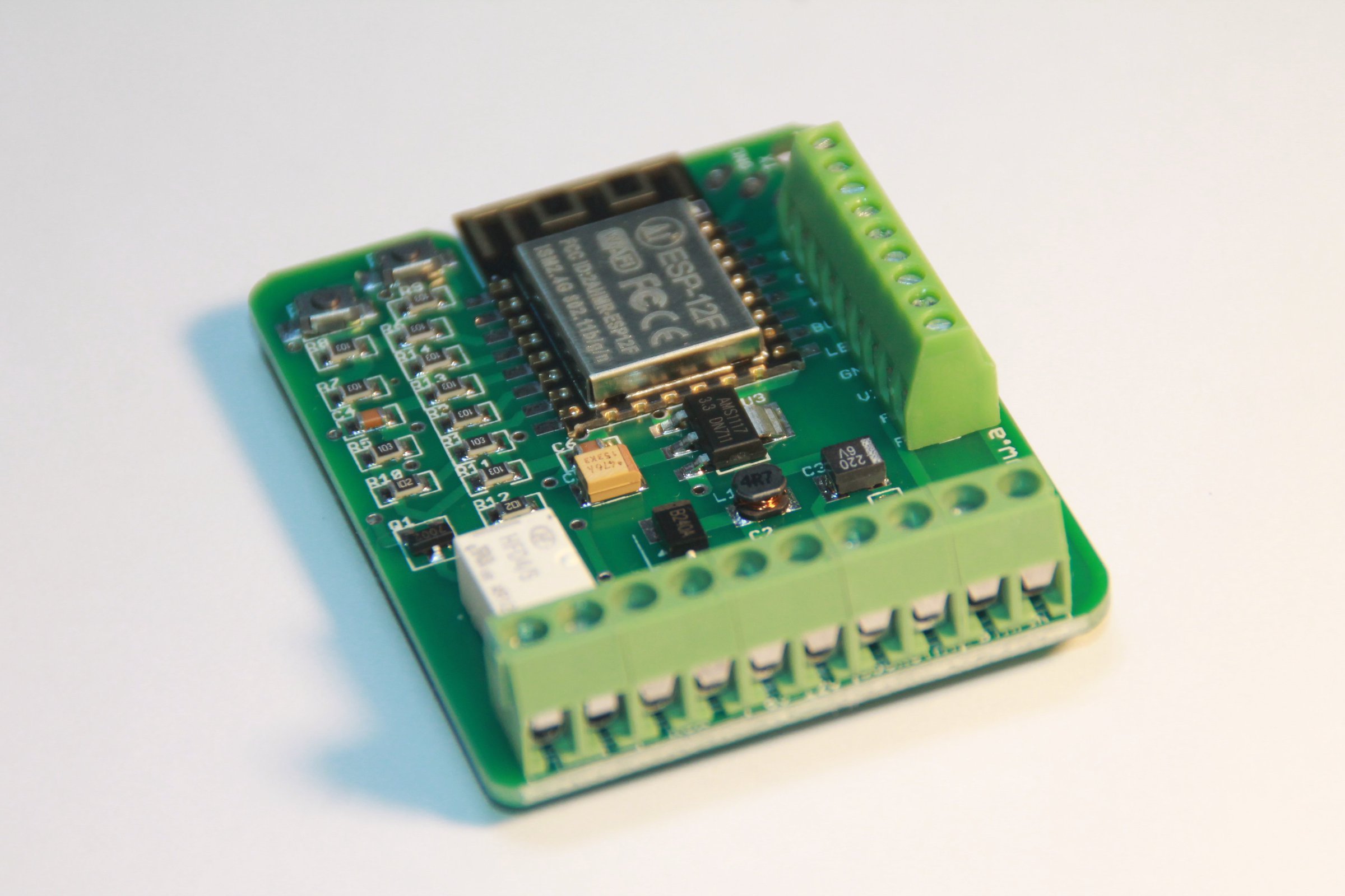
ESP-RFID Relay Board is tiny ESP12 module (ESP8266) board, designed with wiegand RFID readers in mind and ESP-RFID Firmware
- Small size factor, sometimes possible to glue it into existing readers.
- Single power source to power 12V/2A powers ESP12 module, RFID Wiegand Reader and magnetic lock for opening doors.
- Exposed programming pins for ESP8266
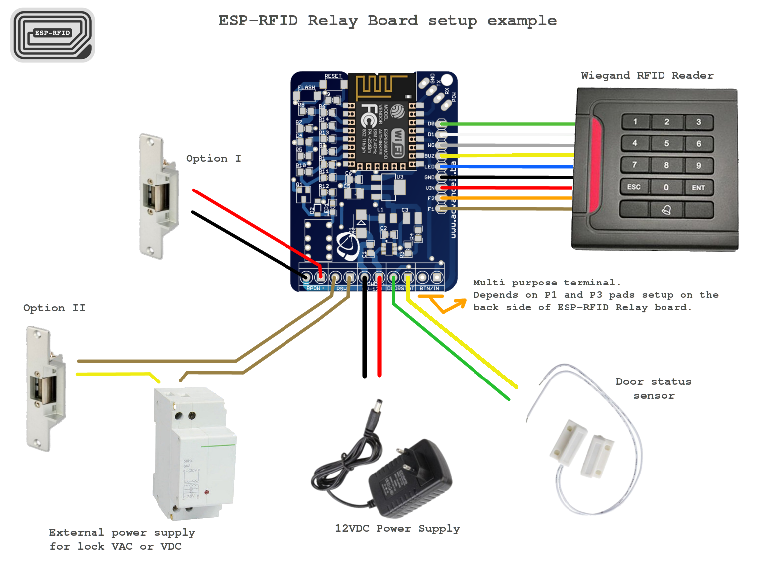
- Due to interesting hardware design, you get multiple possible setup options:
- Forward Bell ringing on reader to MCU or pass it out of board
- Track Door Status
- Control reader’s status LED
- Control reader’s status BUZZER sound
- Power reader, lock and the board through single 12V, 2A PSU
- Optionally power magnetic lock through external AC/DC PSU
- Possible to use any kind and any type of wiegand readers
- Enables you to make IOT Access System with very litle wiring
- Fit in universal enclosures with DIN mount
- Opensource Hardware/Cloud RFID reader/Wifi RFID reader
Same as for any other ESP8266 programmer where you need to put EPS8266 into a specific mode. If you want to upload your program, you would use this buttons to put ESP8266 into FLASH mode. Check programming procedure down.
The reason for 9 pins is to cover the most complex wiegand reader i could fins on the market. Mostly they only have 5 or 6 wires but sometimes, they also have 9 wire versions.
| PINNAME | CONNECTION | DESCRIPTION |
|---|---|---|
| DO | GPIO4 | Wiegand data line D0 (*) |
| D1 | GPIO5 | Wiegand data line D1. (*) |
| WG | GPIO0 | Some readers have WG line which if HIGH/LOW can change Wiegand stream bits. Usually not very important! |
| BUZ | GPIO12 | Almost always Wiegand RFID Readers have Buzzer line which can control piezo buzzer. Due to some inconsistency among readers, i was able to make it work only when i connect this line through 10K resistor and than control it with changing HIGH/LOW on that particular pin, depending what i want. IMPORTANT: P3 Pad on the back of board, can make that line to be connected directly to GPIO or through 10k resistor. Check P3 Pad explanation. |
| LED | GPIO15 | Most Wiegand readers have RED/GREEN status LEDs. Some color is default and if the line is changed HIGH/LOW than the other color appears. |
| GND | GND | Planned for Wiegand RFID Reader GND. |
| VIN | VIN | Connected directly to board’s POWER terminal’s positive pole. (*) |
| F2 | To BTN/IN terminal left pole or to GPIO14 (**) | Rarely Wiegand RFID Readers incorporate one button which is often doorbell switch, but the version that i took as an example for this board has those wires. It’s simply the switch between F1/F2. |
| F1 | To BTN/IN terminal right pole or to GPIO14 (**) |
| TERMINAL NAME | DESCRIPTION |
|---|---|
| RPOW | In case RELAY-POWER pad is connected, when relay connects the circuit, this terminal provides input voltage directly on it’s poles. So the door magnet lock can be powered directly through this terminal. |
| RSW | Since i used small signal relay, it had two sides so another side is also connecting at the same time when relay makes connection but it only cut circuit. So practical use for this terminal can be to power magnetic lock with external source and even AC so that you get buzzing sound when the lock opens and avoid jamming of the lock. (*) |
| POWER 8V-12V | This is the main power source and in some settings only power source that you need. Please provide minimum 2A if you also power magnetic lock and Wiegand RFID Reader from same source, through ESP-RFID Relay Board |
| DOORSTAT | This terminal was planned to accept door status magnet switch. It can be also repurposed since it’s just a "button" connected to GPIO16. |
| BTN/IN | Depending on P1 and P2 Pads connection, it can have different purposes.Check P2/P3 pads description below. |
| PAD NAME | DESCRIPTION |
|---|---|
| P1 | Options: Connected poles 3 and 2 redirects F1 on RFID Reader Terminal to BTN/IN right pole. Connected poles 3 and 1 and you will get GPIO14 to be connected on left BTN/IN terminal, grounded with 10k resistor. Connected poles 2 and 1 and you will power pin F1 on RFID Reader Terminal with GPIO14 (*) |
| P2 | Options: Connected poles 3 and 2 redirects F2 on RFID Reader Terminal to BTN/IN left pole. Connected poles 3 and 1 and you will get 3V3 on left pin of BTN/IN terminal. Connected poles 2 and 1 and you will power pin F2 on RFID Reader Terminal with 3V3 (*) |
| P3 | Options: Connected poles 1 and 2 redirects BUZ pin on RFID Reader Terminal and GPIO12. Connected poles 2 and 3 redirects BUZ pin on RFID Reader Terminal and GPIO12 through 10K resistor. |
| RELAY-POWER | This pad is usually connected if you want to power RPOW Terminal from main power source as ESP-RFID Relay Board |
| 5V/3V3 | Only purpose of this pad is to connect 5V or 3V3 line to PROG’s POW pin. |
The main idea was to be able to adjust this little board to your scenario and also not to occupy few GPIO where there is possibility to use those in some other way.
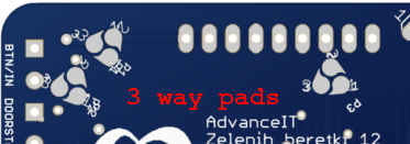
For example, i thought that somebody would like to have remote doorbell but somebody would simple hook it directly. Yet, it might happen that you don’t need doorbell at all but you might find use for GPIO14. So, i made custom PCB Three Way Pad.
Find out about it here:
https://hackaday.io/project/54277-3-way-pcb-pad
https://github.com/nardev/eagle3wayPCBpads
So, it’s similar to other pads which you just solder but this pad has unique shape so it can be soldered not in 2 but in 3 different ways. Just solder it in a way you want. (*) Check the table with description above.
P1 and P2 pads must be set in pair. Essentially you can get one of three different options.
I : You can redirect F1 and F2 on RFID Reader Terminal to BTN/IN terminal.
II: You can redirect input on F1 and F2 on RFID Reader Terminal to ESP8266’s GPIO14.
III: You can redirect BTN/IN terminal to ESP8266’s GPIO14 as button input.
P3 has bit strange purpose. I noticed that most popular wiegand readers have BUZZER line which i couldn’t control directly by simply HIGH/LOW on digital pins of ESP8266 and i also couldn’t find any docs what signal is required, but i found a way for most of readers, it’s simply to put 10K resistor on the line. But, since it varies i also left an option to hook it directly to GPIO12
RELAY-POWER is just connecting positive line to RPOW terminal. Usually, if you power the lock from the ESP-RFID Relay Board, that pad will be connected and you will use RPOW terminal to hook the lock.
5V/3V3 pad can be handy if you are powering ESP12F module through programmer itself while programming.
The relay used on this board is HFD4/5, DPST signal relay and it’s controlled through GPIO13 on ESP8266.
ESP-RFID relay Board is essentially dev board extension for ESP12 modules. As that, it has RESET and FLASH buttons and the rest of circuit required to put ESP8266 in programming mode. In order to program the board, you would need "USB-TTL" or similar compatible programmer. (I personally like this 1$ one here)
Programming Procedure
Considering that you already installed required drivers for your OS and that you have programming software already set, follow procedure:
- Connect your USB-TTL programmer to P ROG terminal. (Don’t forget to cross lines, RX to TX and vice versa)
- Press FLASH and RESET buttons together.
- Release RESET Button and keep FLASH Button pressed for 1-2 sec and than release it too.
- Now, your ESP8266 should be in FLASH mode and you can upload you program. (*) I noticed that it it doesn’t make any problems if you keep FLASH Button pressed and sometimes ESP8266 won’t start with FLASH mode in any other way.
-
Silkscreen mistake WG/LED pins should be switched. (To test with base firmware and setting pins to down/up and to check if that is the case only with ESP-RFID firmware)
-
Sometimes, connected ringing button through board, VAC source and to bell, causes buck converter to jamm. It could be due to poor wire quality or something else. But usually if it doesn’t occur immediately on first try, it never appears later.