Exploring the possibilities of the AS3935 Franklin Lightning Sensor and understanding the electromagnetics behind it. This seems to turn as much into a study of man-made disturbers as of natural lightning strikes.
The AS3935 IC by austria microsystems is a sensitive RF receiver - coupled with a proprietary algorithm - able to detect the specific radio frequency emissions generated by lightning activity. The algorithms distinguish real lightning strikes from from man-made electromagnetic “disturbers” and can calculate the energy and distance of strikes over a 1–40km range.
- draws only 60uA in listening mode
- will issue an interrupt when lightning is detected
- can be interfaced using I2C or SPI
FYI: The AS3935 won AMS the gold award at the 2012 sensor expo. Makes you want to keep track of what sensor win this price in the future :)
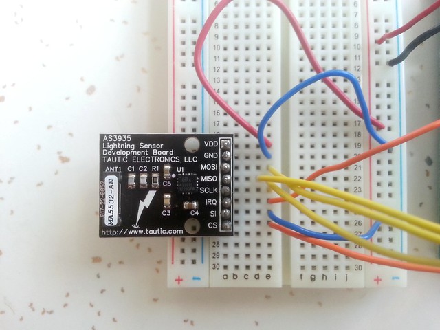
AS3935 Lightning Sensor Dev Board by Tautic Electronics, bought at Tindie which comes with an onboard antenna. All you need to get it working is to connect it up to a microcontroller (currently using Arduino Mega 1280). The Tindie board is setup for SPI communication, but can also enable I2C by soldering some jumpers on the bottomside of the board.
I am using this Arduino hardware library AS3935-Arduino-Library by Raivis Rengelis
I added some minor functionality to the library (see library directory in this repository):
- getBestTune() - automatic calibration returns chosen tuneCapacitor value
- tuneAntenna(byte tuneCapacitor) - manual calibration
- lightningEnergy() - returns energy value (via Striker)
- getIRQ() - to see whats happening on the IRQ pin
Pin-out for Arduino Mega 1280. Powered with 9V battery connected to power jack of Arduino board.
AS3935 breakout board 		Arduino Mega 1280

VDD             			5V (Arduino)
GND            			 	GND
MOSI            			51
MISO            			50
SCLK            			52
IRQ             			2
SI              			GND
CS              			53

lightning LED 				4
disturber LED 				5
thunder 					6
Setup for Arduino Pro Mini 3.3V. If powering Arduino with more than 3.3V, be sure to use RAW pin (and not VCC).
AS3935 breakout board 		Arduino Pro Mini 3.3V

VDD             			5V (Arduino)
GND            			 	GND
MOSI            			11
MISO            			12
SCLK            			13
IRQ             			2
SI              			GND
CS              			10

lightning LED 				4
disturber LED 				5
thunder 					6
Another Arduino library: https://github.com/SkyeSweeney/Striker/
Raspberry-Pi library: https://github.com/pcfens/RaspberryPi-AS3935
Lightning strikes are electrostatic discharge, reacting to the high electric potential btw a thunderstorms negatively charged bottom layer and earth's positively charged ground. Lightning is detected by sensing electromagnetic radiation. The rapidly changing currents of the strike cause electromagnetic pulses (pulse time 10-150ms) in the VLF (3k-30kHz) and ELF (<3kHz) radio bands. The maximum amplitude lies around 5-10KHz.
The hard-coded detection algorithm in the AS3935 is build for a 500kHz signal.
[...] The AMS does not simply look for a peak over a threshold. They look for the multi stage crackling signature of a lightning stroke. Where a series of small events occur before the major stoke occurs. This allows them to filter out noise events from things like solenoids from generating false alarms. 500 kHz was likely picked as it is a section of the RF spectrum that gets little HAM use, hence little interference [...] (https://forum.sparkfun.com/viewtopic.php?f=5&t=32437)
The algorithm seems to look for a signal signature like this:
The incoming signal of the RLC resonator to the IC needs to be tuned to the resonant frequency of 500.000 Hertz, +-3.5% It is tuned by setting the capacitor value (=tuning capacitor) of the RLC resonator. You set the capacitor value (16 discrete options), then you detect the current antenna frequency by counting the square-wave oscillation on the _IRQPin. Then you adjust if the value is not close to 500.000 Hz.
Outputting the frequency values resulting from setting all possible capacitor values:
tune antenna to capacitor 0	 	gives frequency: 3165 = 506400 Hz
tune antenna to capacitor 1	 	gives frequency: 3129 = 500640 Hz
tune antenna to capacitor 2	 	gives frequency: 3118 = 498880 Hz
tune antenna to capacitor 3	 	gives frequency: 3109 = 497440 Hz
tune antenna to capacitor 4	 	gives frequency: 3130 = 500800 Hz
tune antenna to capacitor 5	 	gives frequency: 3119 = 499040 Hz
tune antenna to capacitor 6	 	gives frequency: 3111 = 497760 Hz
tune antenna to capacitor 7	 	gives frequency: 3100 = 496000 Hz
tune antenna to capacitor 8	 	gives frequency: 3090 = 494400 Hz
tune antenna to capacitor 9	 	gives frequency: 3081 = 492960 Hz
tune antenna to capacitor 10	gives frequency: 3039 = 486240 Hz
tune antenna to capacitor 11	gives frequency: 3028 = 484480 Hz
tune antenna to capacitor 12	gives frequency: 3019 = 483040 Hz
tune antenna to capacitor 13	gives frequency: 3041 = 486560 Hz
tune antenna to capacitor 14	gives frequency: 3032 = 485120 Hz
tune antenna to capacitor 15	gives frequency: 3023 = 483680 Hz
Problematic: the frequency values vary over time!! Either due to faults in the measurement (no reliable clock) or due to environmental influences on hardware? Changes to the IC thresholds seem to change the antenna frequency values, and therefore require recalibration calls?
Apparently the chosen antenna on the board should determine the tuning value. I've read online that the Tindie-board capcitor value should be 5. Yet when i run the automatic calibration procedure, it usually picks either 0, 1 or 2. I've implemented a funciton to manually set it to 5, but i can't quite tell yet the effect of the different settings on the results.
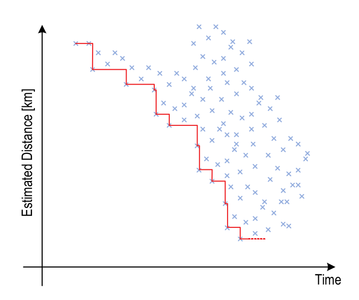
Successful lightning strike detection results in an energy value and a distance value (discrete steps, limited to: 0, 5, 6, 8, 10, 12, 14, 17, 20, 24 ..). The distance corresponds to the distance of the storm head instead of the distance to the last lightning strike. The system stores all recent lighting strikes and uses them to calculate the storm head.
Action at a distance! Activating a solenoid (6V) within the same room (couple meters in between) definitely causes the disturber interrupt to go off. The solenoid EM-pules is detected on disrupting the solenoid circuit (when nail is again released from coil). This can be a good tester to verify the circuit is working, though reports online say, that disturbers going off doesn't necessarily mean the system is properly calibrated.
possible sources of EMI (electromagnetic interference):
- piezo BBq lighter
- noisy electric drill, electric motors
- ignotion system of motor cars
- appliances
- fluorescent lights
- Tv sets
- light switches
- high voltage wires
- solenoid
Running the Arduino on a 9V battery, flashing an LED for disturber interrupts, i investigated my apartment for disturbers. I noticed: increase in disturbers if i hold the antenna at a specific distance (~5-10cm) at a specific angle to a light source. Doesn't seem to work for incandescent bulbs though.
Calibrating the chip has been the major issue so far. The chip has several values that need calibration to avoid false positives:
- noise floor threshold : 0...7
- watchdog threshold : 0...7
- spike rejection threshold : 0...7
- AFE gain : setIndoors..or..setOutdoors
Good practice is to recalibrate after every setting change.
Others report:
- setting it too sensitive make it less sensitive to local strikes, and setting it less sensitive makes it less sensitive to remote strikes (http://www.wxforum.net/index.php?topic=22235.75)
- grounding the chip (to mains ground) reduces the number of strikes it reports, better battery power (http://www.wxforum.net/index.php?topic=22235.75)
There's only been one proper thunderstorm since i've played with the board. But at least i managed to collect some data with visual verification. These are the settings that produce accurate results. Definitely less strikes than i noticed by eye, but at least the reported strikes corresponded to real lightning strikes.
I got the best results when activating the IC's outdoor setting. No matter if it actually was physically outdoors or indoors. Though i eventually packed the Arduino and the chip into a ziplock bag and stuck it out the window to get rained on.
noisefl | spike rej | watchdog | indoor/outdoor | tuneAntenna
Sept 5th
0,0,0,outdoors > 37km, 20km, 20km
0,0,0,outdoors,5 > 40km, 37km, 34km, 34km, 27km
1,0,0,outdoors,5 > 27km, 24km,

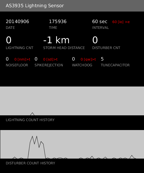
The processing app p5_control_and_log is used for monitoring the activity of the IC. It logs the output to a .csv file and displays the current parameters and a short history of lighting and disturber counts. It also takes screenshots every hour.
For it to work, you need to have the AS3935_log_cnts sketch running on the Arduino.
- antenna capacitor tuning changes over time? or is due to hardware (antenna)?
- difference btw intra-cloud and cloud-to-ground lightning?
- what are the man-made disturbers in my environmet?
- should the antenna/IC be placed at a distance from the Arduino?
- orientation of antenna matters?
- setup should not be grounded? use opto-isolators for the SPI lines?
- better if not connected to computer?
- what is a normal disturber count? 10 / sec
- difference in detection approach btw AS3935 and analog lightning-detection circuits?
- http://www.digikey.ca/en/articles/techzone/2013/mar/incoming-storm-a-lightning-detector-from-ams
- http://www.electronicproducts.com/Sensors_and_Transducers/Sensors_and_Transducers/Designing_truly_portable_lightning_detectors.aspx
- http://www.rs-online.com/designspark/electronics/blog/detecting-lightning-with-an-arduino
- http://coffeewithrobots.com/detecting-lightning-with-a-raspberry-pi/
- http://fll-freak.com/blog/?p=554