SparkFun Load Cell Amplifier - HX711
The SparkFun Load Cell Amplifier is a small breakout board for the HX711 IC that allows you to easily read load cells to measure weight. By connecting the amplifier to your microcontroller you will be able to read the changes in the resistance of the load cell and with some calibration you’ll be able to get very accurate weight measurements. This can be handy for creating your own industrial scale, process control, or simple presence detection of an object.
The HX711 uses a two wire interface (Clock and Data) for communication. Any microcontroller’s GPIO pins should work and numerous libraries have been written making it easy to read data from the HX711.
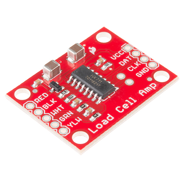
Load cells use a four wire wheatstone bridge to connect to the HX711. These are commonly colored RED, BLK, WHT, GRN, and YLW. Each color corresponds to the conventional color coding of load cells:
- Red (Excitation+ or VCC)
- Black (Excitation- or GND)
- White (Amplifier+, Signal+, or Output+)
- Green (A-, S-, or O-)
- Yellow (Shield)
The YLW pin acts as an optional input that is not hooked up to the strain gauge but is utilized to ground and shield against outside EMI (electromagnetic interference). Please keep in mind that some load cells might have slight variations in color coding.
- /Production_Files - Panelized version of the design for production
- /datasheets - Datasheet for HX711 IC
- /firmware - Example Arduino sketches
- /hardware - All Eagle design files (.brd, .sch)
- Library - Arduino library for the HX711
- Getting Started with Load Cells - Introduction to Load Cells
- Hookup Guide - Basic hookup guide for the Load Cell Amplifier
This design is OSHW and public domain but you buy me a beer if you use this and we meet someday (Beerware license).